Wave disturbance study of Pigadia port, Karpathos
The wave disturbance is a supportive study to the main study entitled "Technical Studies for the Expansion of Karpathos Port" commissioned to CNWAY in November 2013.
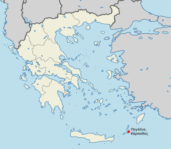
Karpathos is the second largest Island of the Dodecanese complex located in the Southeast Aegean sea between Rhodes and Crete. The Island's main port facility is located within Pigadia Bay, at its southeastern side, which serves as a portal for passengers and goods arriving on the Island.
Objective
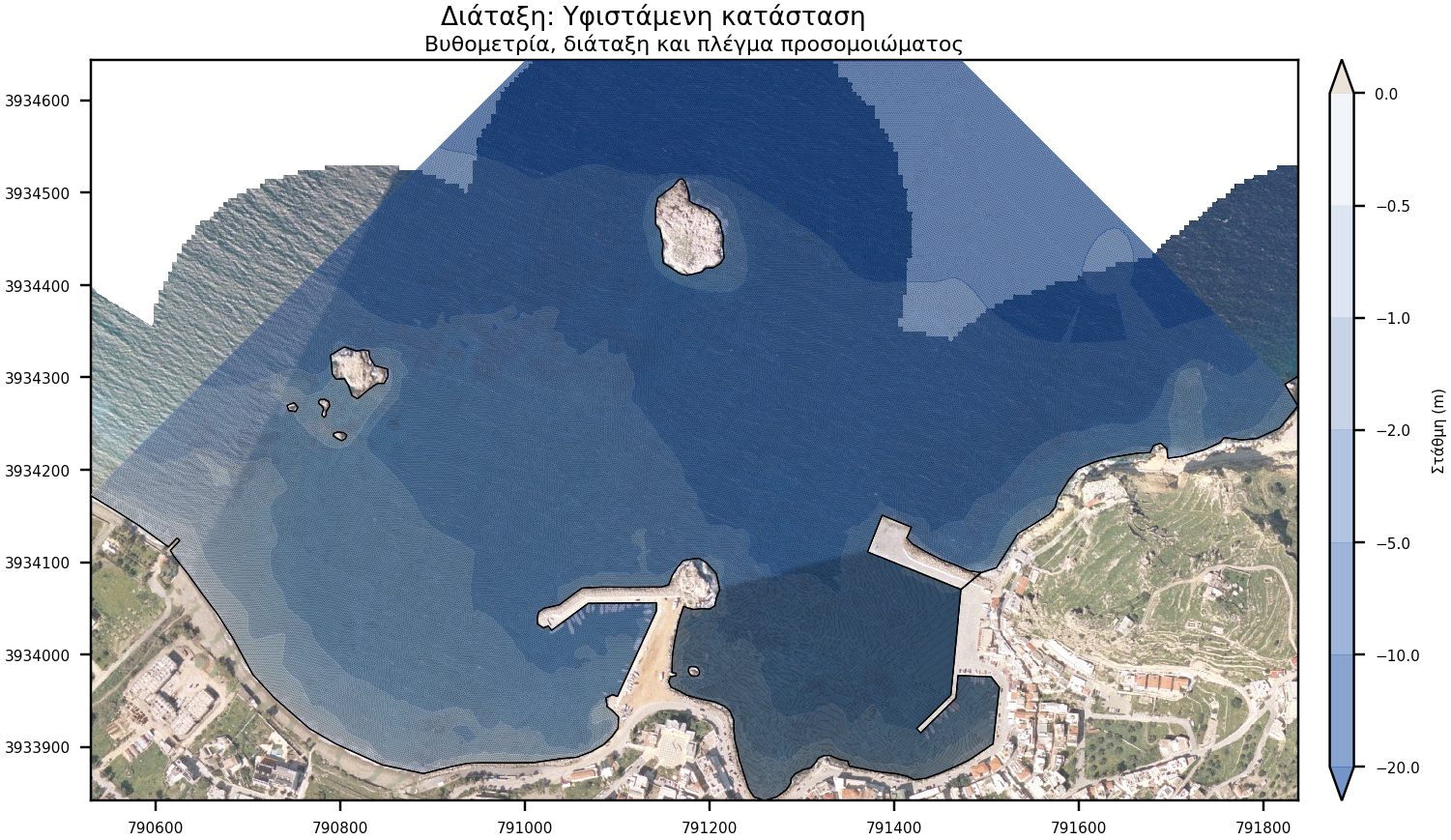
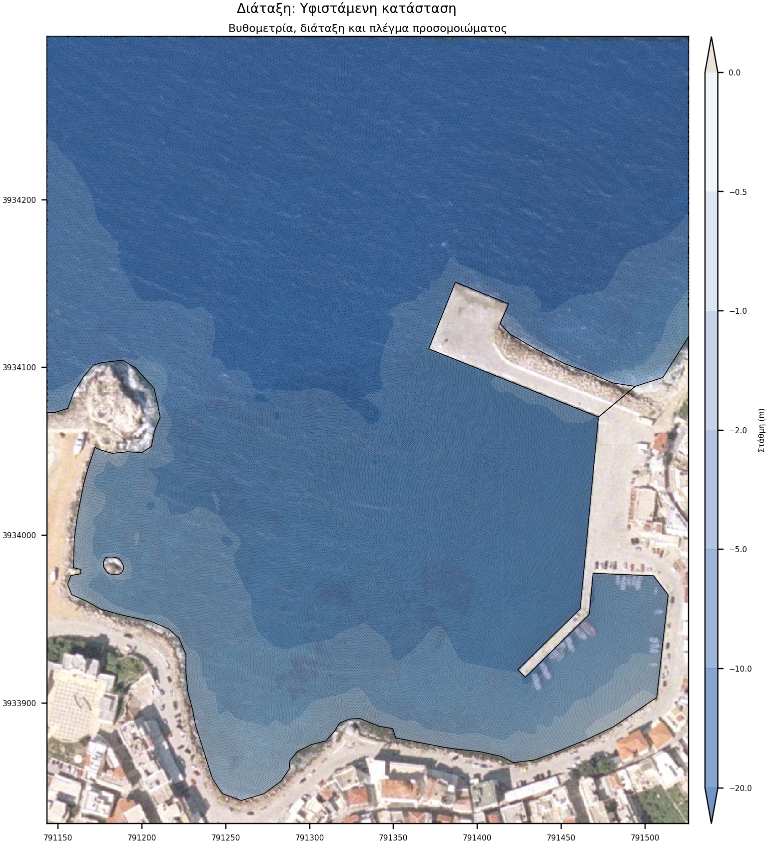
According to the Urban Master Plan, the location of the new works is to the east and north of Garonissos Island and includes a new quay and access corridor. The entrance of the new basin, will be created by dismantling approximately 70m of the existing breakwater.
The purpose of the study is to investigate the berthing conditions within the proposed new port and in particular the impact on the new opening on the existing eastern quay walls on the lee.
Numerical modeling
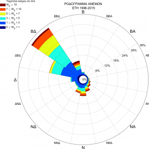
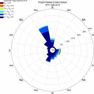
Wave climate
Wave and wind data are derived from the WAMC4 and Skiron/Eta forecast model from node 946_192 with latitude and longitude 35.50o, 27.25o. The location is 3.3 kilometers away from the project site. The duration of the data covers the period from 1-1-1996 to 31-12-2015.
Modeling characteristics
The overall simulation is usually performed by two separate models, the offshore and the wave disturbance model. The former extends from the position of offshore wave conditions (the node of the WAM wave model) up to the shore, and its role is to define the boundary conditions for the wave disturbance model.
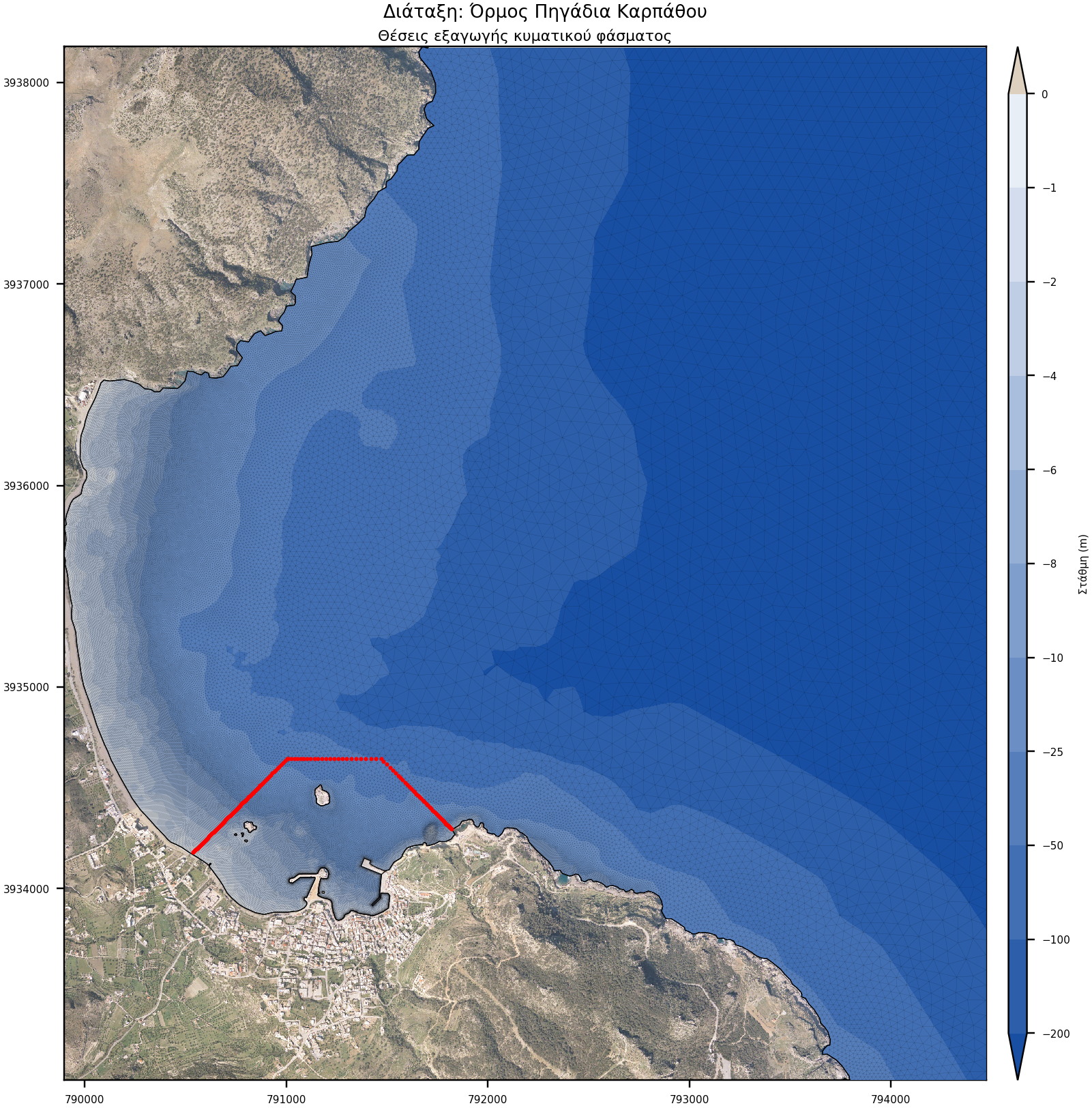
- Offshore simulation: It extends 5.1 km along the N-axis and 4.6 km laterally. It covers an area of approximately 17.1 km2 and consists of 177,000 elements and 90,000 nodes
- Wave disturbance simulation: It extends 1300 meters along the DA axis and 800 meters laterally. It covers an area of about 645 acres. and consists of about 445,000 elements and 224,000 nodes
A total of 20 wave cases corresponding to 100 simulations were executed, which consist of:
- 20 TOMAWAC simulations to propagate wave conditions from the WAMC4 regional model node to the project location,
- 80 ARTEMIS simulations, for the calculation of wave disturbance, 20 for every wave case, 4 layouts (Existing, Alternatives 1, 2 and 3).
Results
For further analysis and objective comparison of the results, areas of interest have been defined for every layout. For each area, the following parameters have been calculated:
- Active (Ηm0(rms)) and maximum wave height (Hm0(max)) for absolute disturbance and
- Active (Ηm0(rms),), maximum (Hm0(max)) and minimum wave height (Hm0(min)) for differential disturbance
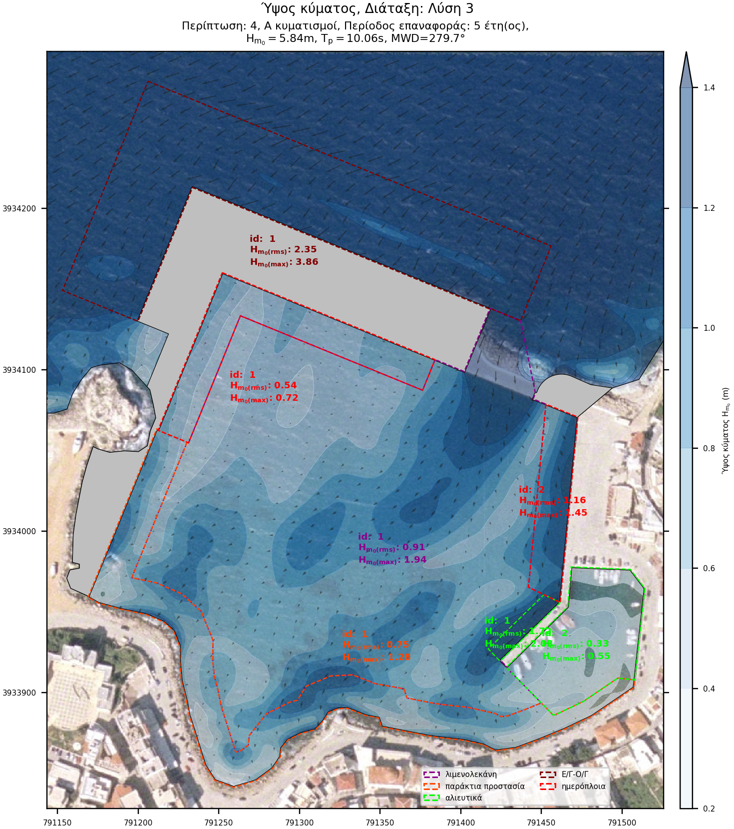
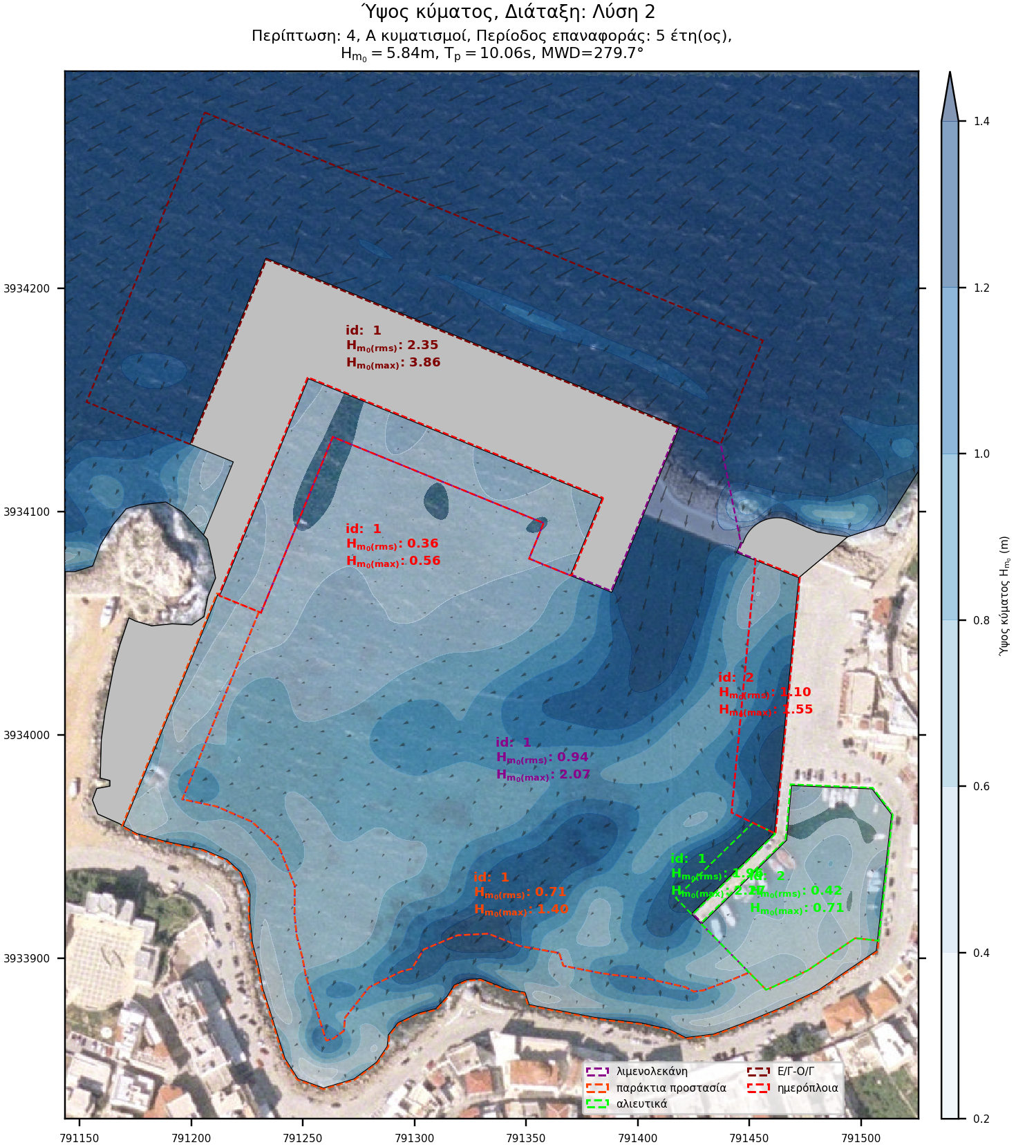
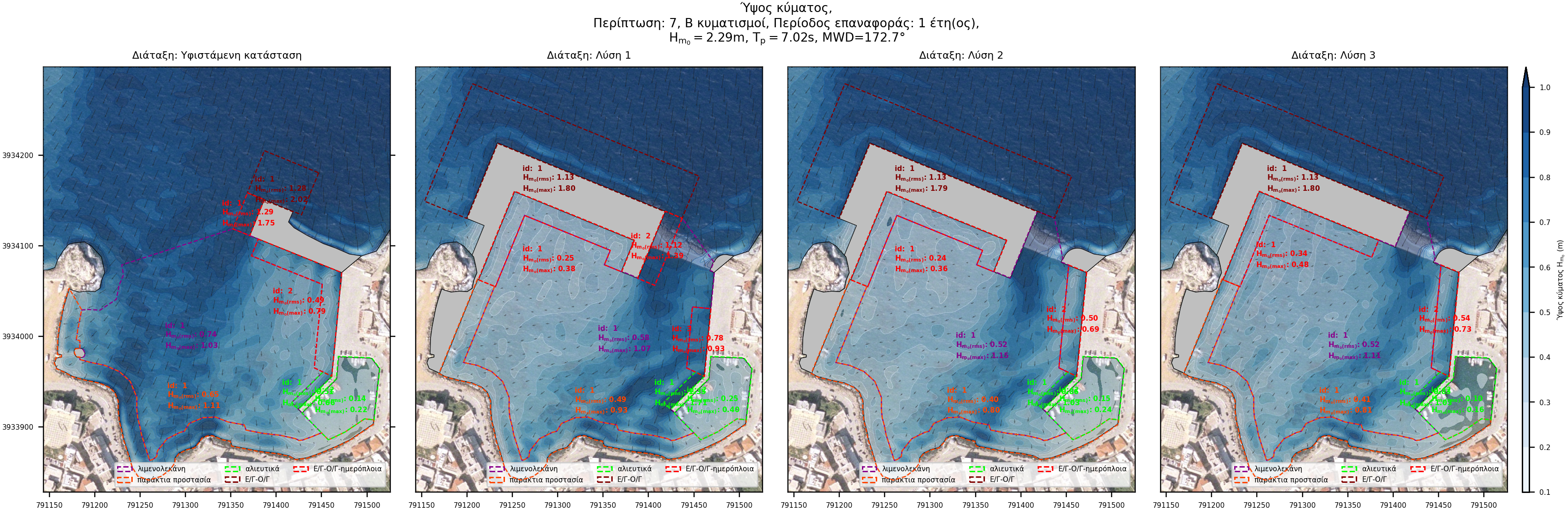
Absolute disturbance plots
The diagrams of the absolute wave disturbance show the results of each layout for each wave case, as derived from the simulation.

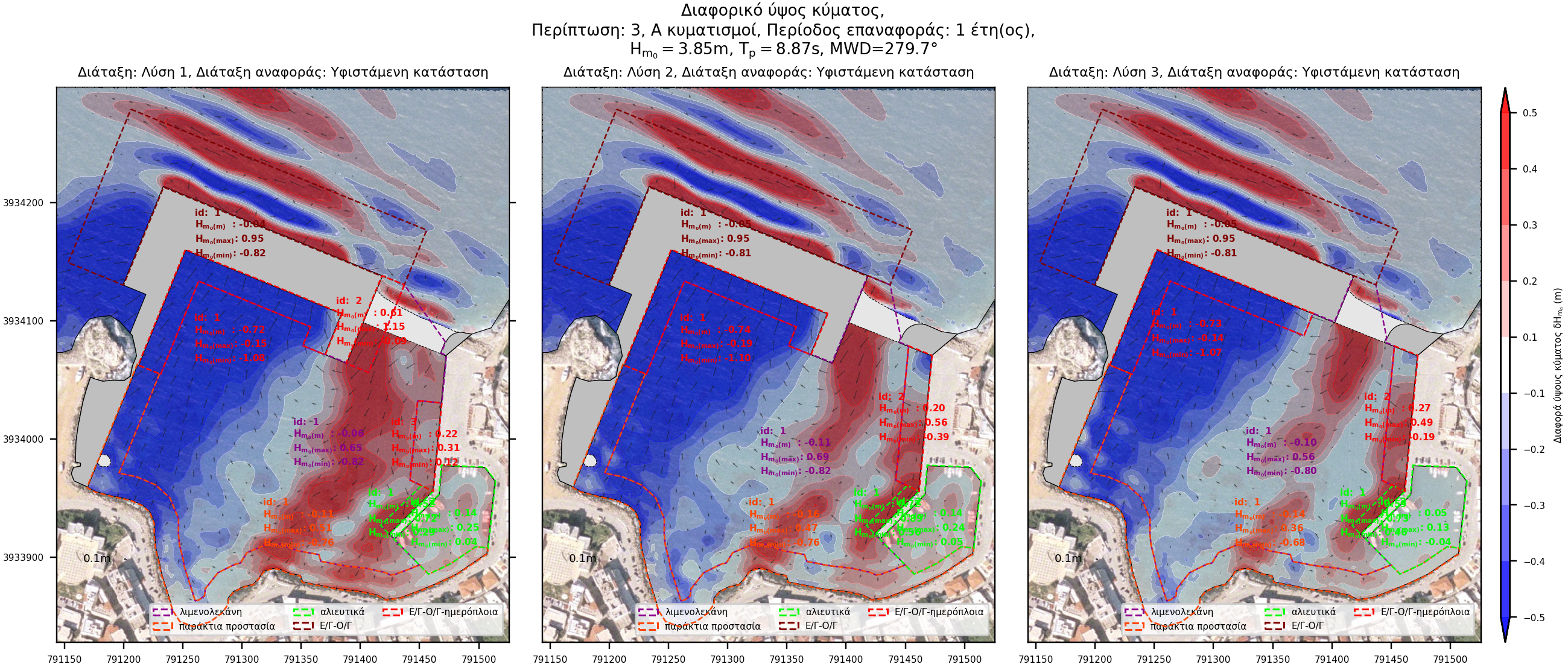
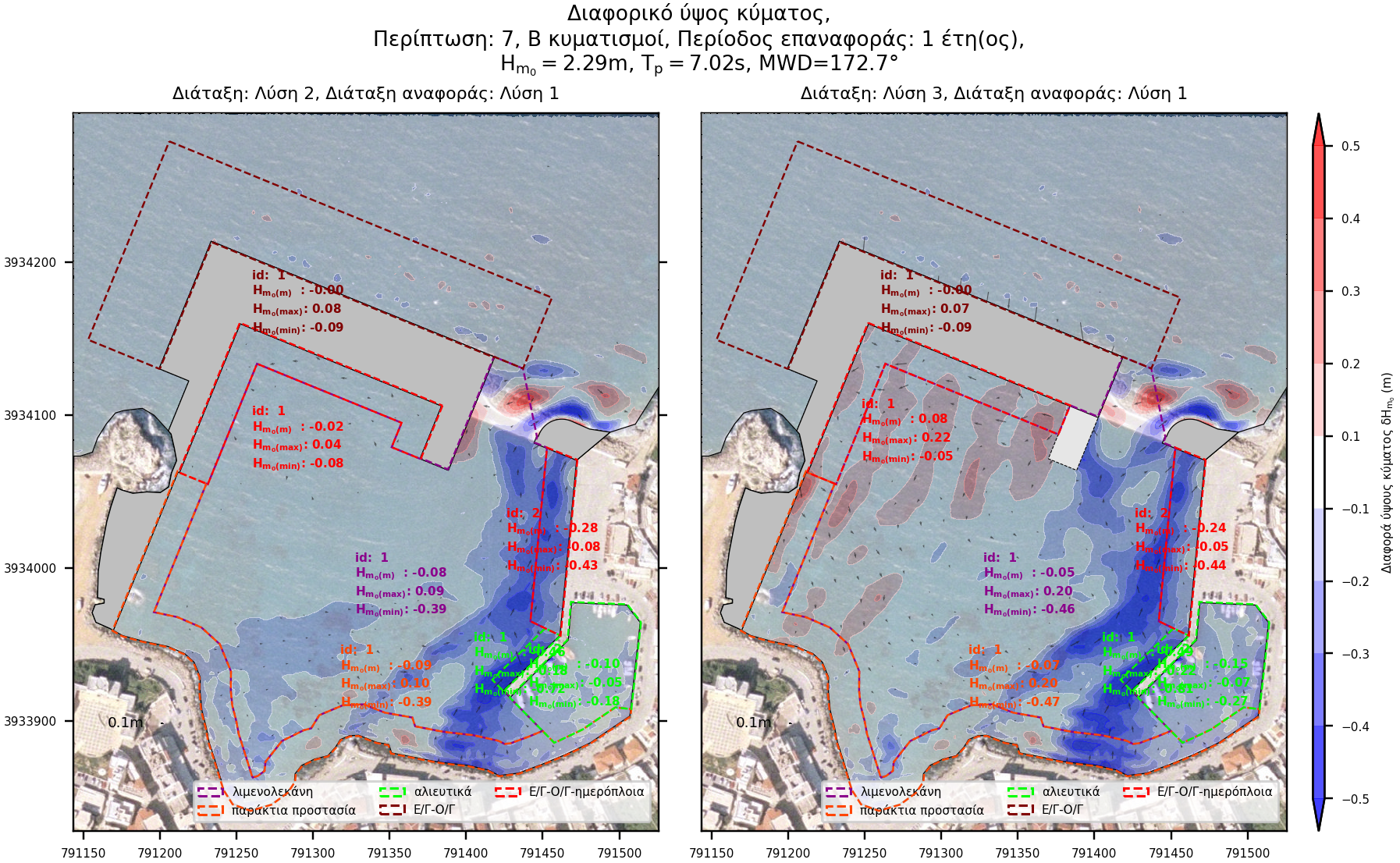
Differential disturbance plots
The differential disturbance diagrams result from the algebraic subtraction of the wave disturbance between the compared layouts. The "Reference Layout" disturbance is subtracted from the disturbance of the solution under consideration. This results in a positive differential disturbance (red gradient) when the layout under consideration causes more disturbance than the reference layout. Conversely, a negative differential disturbance (blue gradient) means the layout under consideration causes less disturbance than the reference layout.
This easily identifies the positions as well as the extent to which each layout has an advantage / disadvantage over the "Reference layout". Below is an example:
- Differential wave disturbance with respect to the Existing layout.
- Differential wave disturbance of the 2 alternatives layouts (Alternatives 2 and 3) with respect to the layout originally proposed (Alternative 1)
Qualitative analysis
The score is calculated using an evaluation model that takes into account the following wave disturbance parameters for each zone:
- Active wave height (Hm0(rms)),
- Maximum wave height (Hm0(max)),
- Wave height exceeding predefined limits of allowable disturbance (Hm0(exc)),
- Zonal percentage area exceeding predefined limits of allowable disturbance (PAexc).
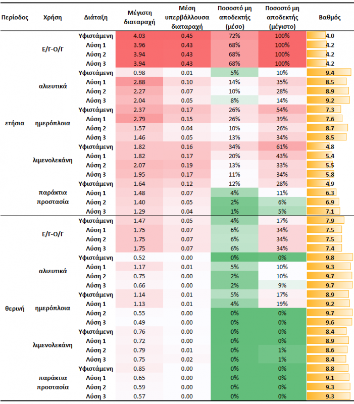
Conclusion
The study of the wave disturbance carried out shows that the wave disturbance the Existing conditions (Solution 0) offers satisfactory mooring conditions, but the port does not provide the required protection. The originally proposed layout (Solution 1) faces increased disturbance on the lee of the opening due to its large opening. The reduction of the entrance width by 30m proposed in Solution 2, reduces the disturbance overall except for the fishing shelter zone. Further modification of the layout with Solution 3 significantly improves the disturbance in the fishing shelter, reducing the burden of day-time vessels.
Out of all the solutions considered, solution 3 results in the best wave disturbance conditions overall and at the same time reduces the construction costs and therefore is the proposed one.