Wave disturbance study of Aghia Kyriaki, Trikeri
Project location
Agia Kyriaki fishing harbour is located on the east side of the entrance of the Pagasitic Gulf and 18 nautical miles from the Volos port. It mainly supports the flourishing fishing activities of Ag. Sunday and Trikeri. The purpose of the study was to investigate wave disturbance of existing and of proposed works and to estimate their expected annual downtime.
Numerical modeling
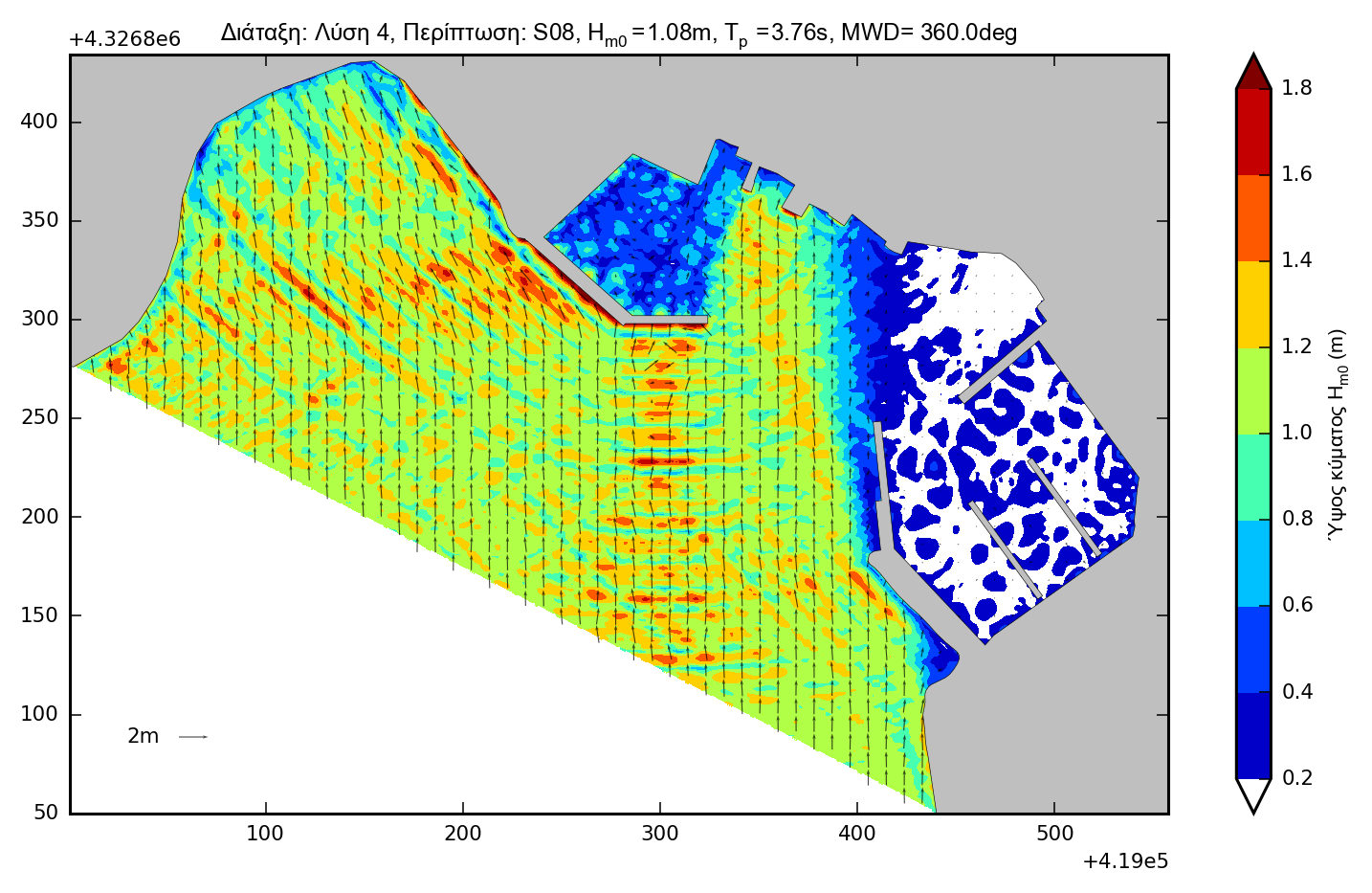
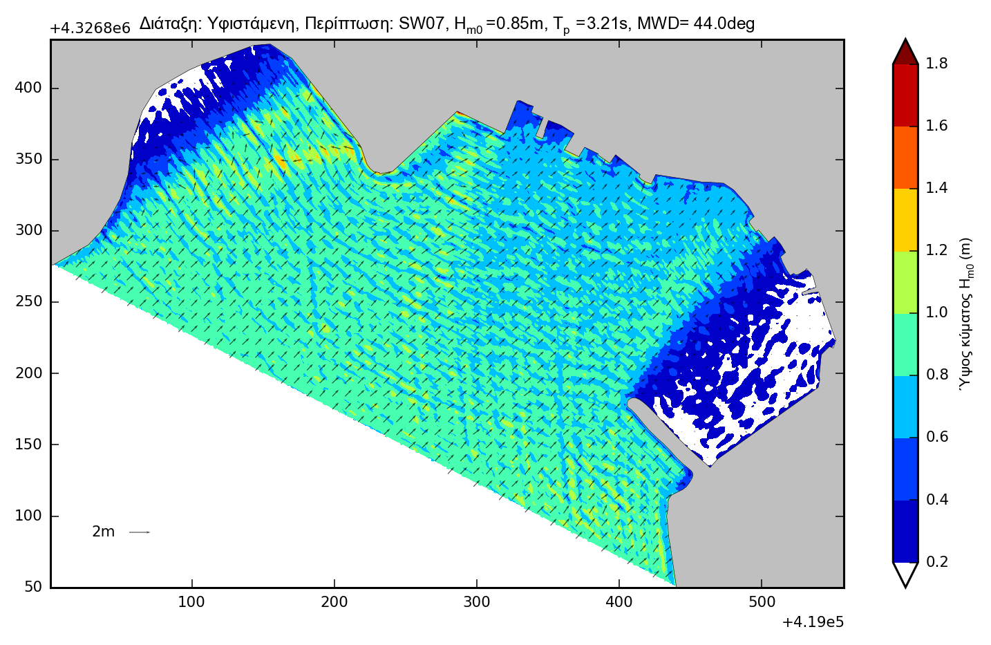
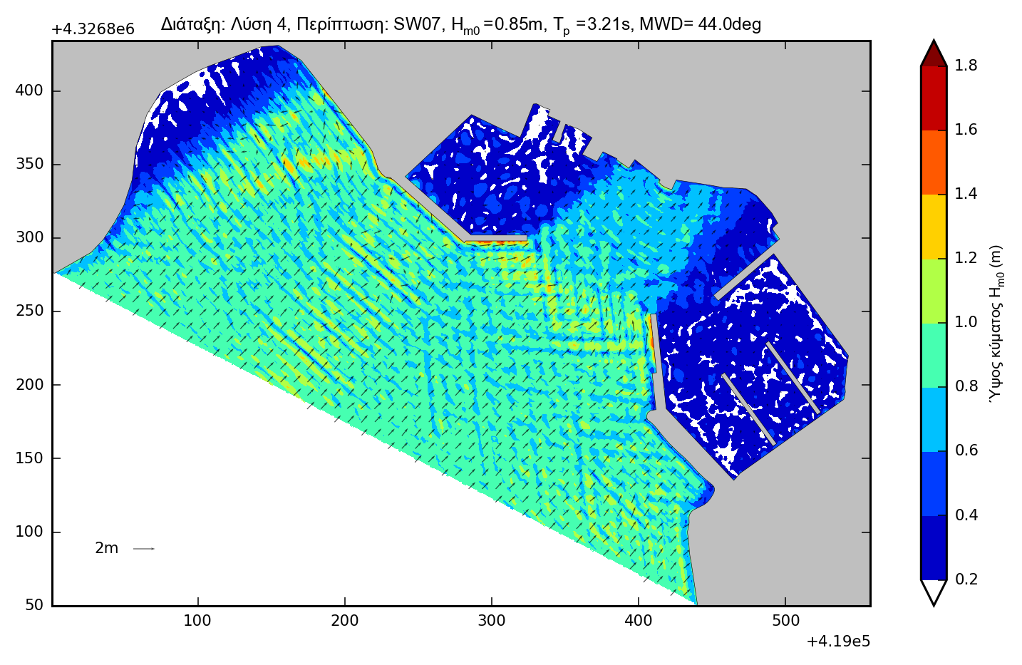
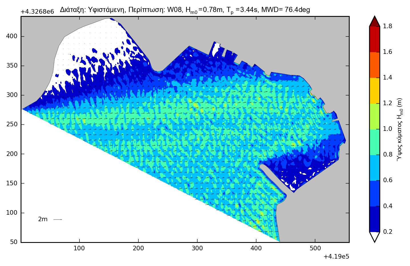
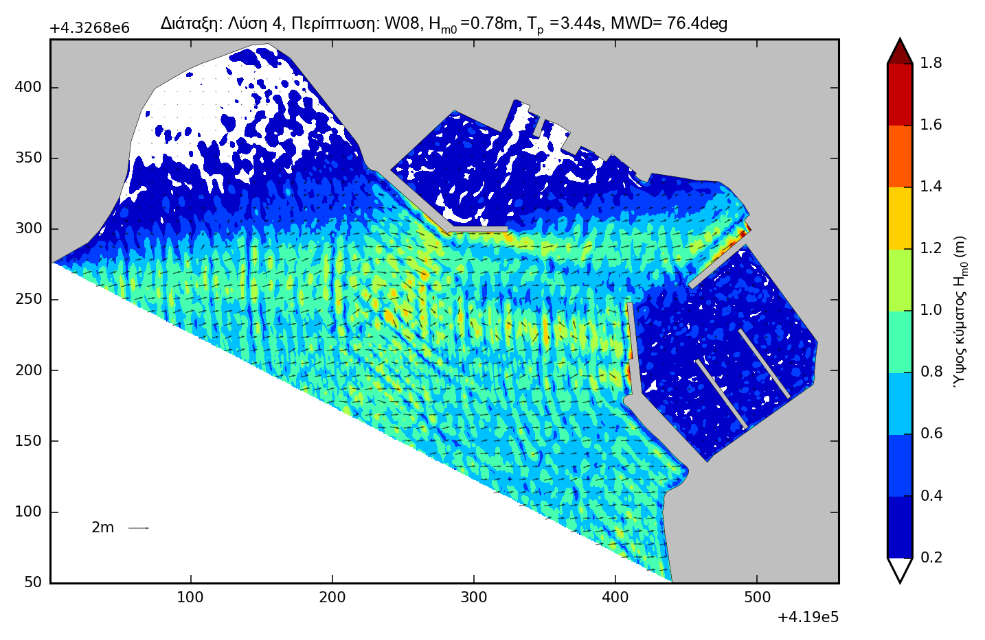
Offshore wave characteristics were calculated by means of the Seaworks computing suite (JONSEY model) and wave disturbance simulation was performed using the ARTEMIS numerical model of the TMS (Telemac-Mascaret System) numerical suite of solvers, based on the solution of elliptic equations.
Simulation facts:
- Dimensional grid of 1050x400 meters,
- 620,000 elements and 312,000 knots
- 7 project layouts, one existing and 6 alternatives to the proposed projects
- 3 wind directions were examined and
- all observed wind intensities of 5bf or more (11 cases for each project layout). A total of 77 numerical simulations were performed.
Results
The effectiveness of each alternative is evaluated both qualitatively and quantitatively. Qualitative evaluation of wave disturbance is performed by graphical inspection of the results and qualitative by mathematical analysis.
Qualitative evaluation
The graphic comparison of the wave disturbance is done in two ways:
- Absolute wave disturbance plots
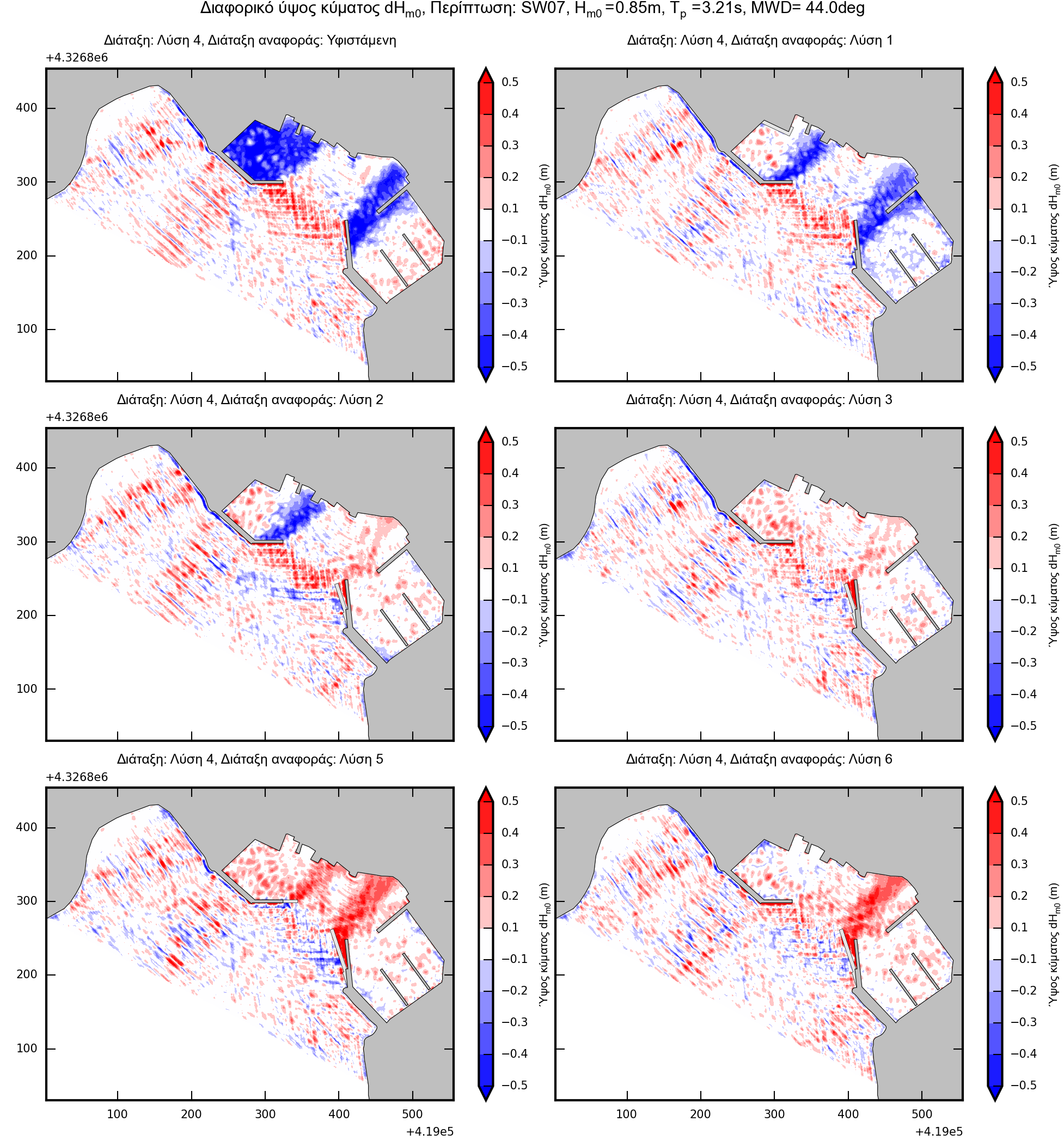
- Differential wave disturbance plots
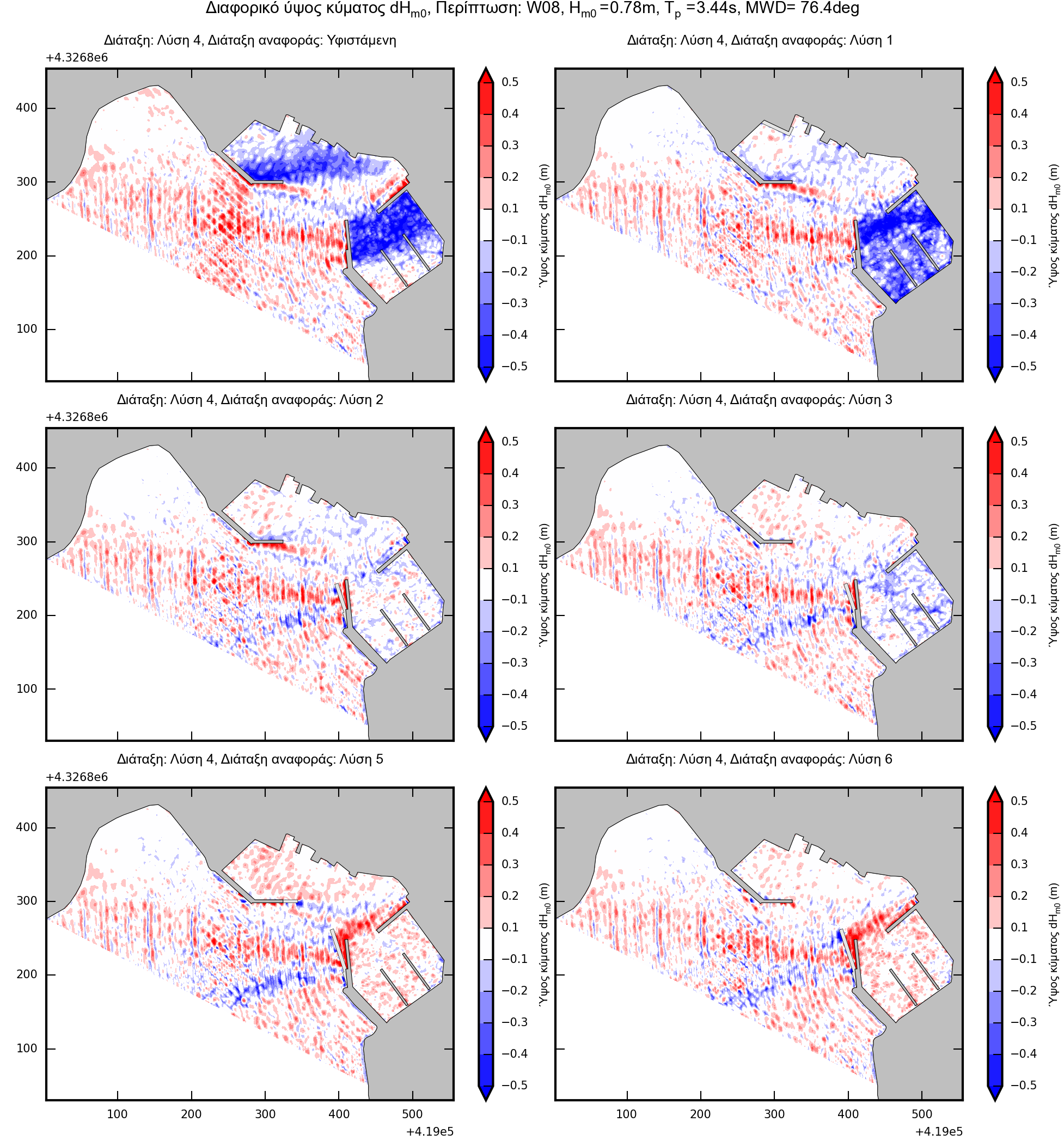
Of the above, differential disturbance plots are of greater interest. They result from the algebraic subtraction between the wave disturbance results of the layouts to be compared. The disturbance of the "Reference" layout is deducted from the disturbance of the layout under consideration. The resulting differential plot is positive (red gradient) when the layout under consideration causes more disturbance than the reference solution. Conversely, it is negative (blue gradient) when the layout under consideration causes less disturbance than the reference layout. This easily identifies the locations and the extent to which each layout has an advantage / disadvantage over the others. The following are the differential wave disturbance of an alternative compared to the rest, for 3 different wave cases:

Quantitative evaluation
Mathematical analysis of wave disturbance is an objective criterion for comparing and evaluating solutions. It is done by calculating the active Hrms wave height in each harbor basins (north and south), as summarized below.
| Wave height Hrms (m) | ||||||
| North basin |
South basin |
|||||
| S08 | SW07 | W08 | S08 | SW07 | W08 | |
| Exist. | 1.18 | 0.80 | 0.38 | 0.25 | 0.20 | 0.38 |
| Alt. 1 | 0.97 | 0.27 | 0.29 | 0.32 | 0.36 | 0.66 |
| Alt. 2 | 0.94 | 0.25 | 0.25 | 0.24 | 0.25 | 0.36 |
| Alt. 3 | 0.51 | 0.24 | 0.24 | 0.20 | 0.25 | 0.42 |
| Alt. 4 | 0.53 | 0.33 | 0.27 | 0.21 | 0.27 | 0.33 |
| Alt. 5 | 0.43 | 0.20 | 0.20 | 0.18 | 0.25 | 0.29 |
| Alt. 6 | 0.52 | 0.29 | 0.24 | 0.18 | 0.24 | 0.28 |
Depending on the type of vessel berthed in each basin, its operating times can now be derived.